Assembling a computer step by step
14 Marzo 2023Ultima modifica: 25 Settembre 2023
After reading our previous material on selecting individual components, you already know what to look for when selecting computer hardware. So it's time to turn all the components into a working unit.
This material is mainly intended for people who have never before had to deal with assembling a PC with their own hands. The whole process of assembling a computer, contrary to appearances, is very simple and can be compared to assembling a set of LEGO™ bricks, you only need to pay attention to some details and slightly reduce the use of force, and you will certainly succeed in safely assembling the computer for the first time.
There are at least as many ways to assemble a computer as there are methods of applying paste to a processor. We’ll get to paste and the processor in a moment, but we want you to know that as many specialists in the field there are as many opinions and methods, and in this material we’ll describe one of them.
Preparing for assembly
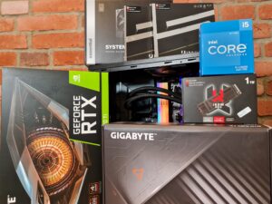
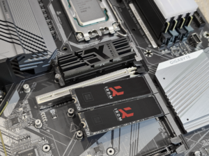
At the very beginning, it is worthwhile to get acquainted with the components we have in our possession. To be able to assemble a computer, we need compatible components, such as a case, motherboard, processor, RAM modules, power supply and at least one free storage medium, such as a GOODRAM or IRDM series SSD of your choice that allows you to install any operating system.
- All components
- Recommended components
- The final result we are aiming for
Of the tools, the following will come in handy: a long Phillips screwdriver for mounting the CPU cooler, a short Phillips screwdriver for mounting the rest of the components (including the motherboard to the case), the recommended thermal conductive paste (since the original paste on the cooler is not always worth looking at), disposable wipes or paper along with alcohol (preferably isopropyl) to degrease the CPU before applying the thermal conductive paste.
It’s also a good idea to prepare yourself and get rid of electrical charges from your body, which can be generated if you have carpet or electrically susceptible clothing. I think everyone has at least once encountered the phenomenon when, after touching a metal component or another person, they felt a strange stinging sensation created by a jumping spark – such a spark can kill a component that you are about to touch while assembling your computer. To protect against this phenomenon, it is worth arming yourself with a mat/pad and an antistatic (ESD) band. However, if you do not want to spend extra money on equipment that is used by professional services, then at home you can get rid of electrical charges by touching a metal component that is grounded, and ideally a radiator will work for this purpose – this is no joke! This procedure can save your expensive equipment.
Step 1 Preparing the motherboard

This is the most difficult step, which consists of several minor steps. At this point you need to pay special attention to the movements, since you will have the most contact with the most delicate components of the computer. At the very beginning, you should start with the motherboard and its preparing for later installation. Take the board out of the box and out of the anti-static foil in which the new motherboard is sure to be wrapped. Try not to put the board on this foil, as it only serves its purpose if it “hides” the electronics inside. Otherwise, the board may be damaged by a sudden electrostatic discharge. We recommend using the cardboard packaging just from the motherboard as a stand during further assembly.
The next step is to mount the processor in the board, and this step varies a bit depending on what brand of processor you intend to use.
Step 1.1 Mounting the processor
In the case of motherboards for INTEL processors, special attention must be paid to the processor socket (socket), because there are hundreds of small pins in it, the twisting or complete breaking of which will most likely lead to damage. Lift the jack, which is located right next to the socket so that all the vulnerable pins appear.
- Grab a lever
- Unlock and move to the open position
- Open the protective cover
- Socket ready for CPU installation
Each socket has its own landmarks for the processor, and in this case it is a small triangle usually in the lower left corner of the socket. On the processor you will also find identical markings in one of the four corners.
- Markings on the processor
- Markings on motherboard
When the socket is open, pull out the processor and gently, without force, place the processor in the socket. When you feel that it has settled into the proper grooves (it does not move from side to side and statically lies covering all the pins), you can gently lay down and hook the pressure cover with the jack still up. You don’t have to remove the black protective cap yourself, which is definitely on the component that presses the processor (CPU) against the socket. This black protective piece will detach itself when you properly close the jack. All you have to do is push it down in the opposite direction of opening and the CPU sits in place. The safety lever likes to put a little resistance, so don’t be afraid to press it down.
- Correctly placed CPU
- Initial CPU protection
- Correctly installed CPU
With AMD processors, on the other hand, we will most often encounter the opposite design compared to INTEL. Since the most common AMD processors have the pins on the processor, so the processor is the most delicate component. Damage to the “feet” of the processor will result in the same effect as if the pins inside the socket are damaged. The assembly stage for AMD processors is very similar to INTEL processors, except that we do not have any pressure tab. It is enough to lift the jack up, thus the socket will slightly move in one direction for us. The markings for the correct seating of the processor are very similar, that is, we are looking for a small triangle in one corner of the socket. We must find the same triangle in the corner of the processor. The markings must coincide with each other. Insert the processor and tighten the socket lever. At this point you have correctly mounted your processor.
Step 1.2 Installing the RAM modules
Once the processor is properly installed, during this step it is also a good idea to unpack the RAM modules and install them. To do this, it is necessary to open one (top) or two (top and bottom) latches securing the modules.
- Space for RAM modules
- Open latches on top
- Open latches on bottom
Lightly apply the modules to the RAM slots and check the fit of one tab with the notch on the board (PCB) of the memory module. When it is certain that the module has not been applied inversely – then it remains only to press the modules into the slot until you hear the characteristic click of the latches.
- Checking for correct insertion
- Evenly pressing the module
- Correctly installed RAM module
- Correctly installed all modules
To take full advantage of the bandwidth of the modules, it is necessary to pay attention to the order in which the RAM slots are occupied. Most often, the first pair for RAM modules is marked with an asterisk on the motherboard.
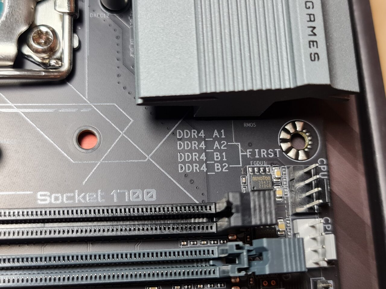
If you can’t find or read such markings correctly, it’s worth looking at the motherboard manual so you don’t make a mistake at this stage. Most often it is the second and fourth RAM slots (of four) counting from the side of the processor socket for the first pair. If you plan to fill all banks (slots) of RAM – you can forget about this step and only pay attention to the correct installation, as the order does not matter. Remember to use modules with the same parameters, otherwise they will work with the parameters of the weakest module, and in the worst case they will not work at all due to incompatibility.
Step 1.3 CPU cooler installation
The last step that is important when preparing the motherboard is to put the cooling on the processor, when you plan to install a cooling consisting of a heatsink and a fan, because at this stage it is easiest to hook up the fan supply to the motherboard. Prepare the heatsink from the cooling and all mounting components, including the backplate (one of the main mounting components, attached from the back of the motherboard) of the entire cooling according to the manufacturer’s instructions – most manufacturers use their own dedicated mounting steps, so it’s worth looking into the said instructions.

It is a good idea to clean the heat sink (IHS) of the processor with isopropyl or regular alcohol. At this stage it is necessary to apply thermal conductive paste. Proven methods of applying paste are many, but the most commonly recommended and proven method is to apply paste in the shape of a large “X”. Besides, you can find methods with three stripes, pea grains or full spreading of the paste on the processor with sticks or spatula, which is often added to the kit with the paste.

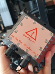
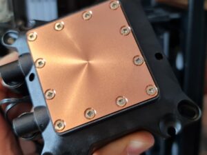
Don’t forget to peel off the protective film from the cooling stand and screw the cooling to the backplate you prepared earlier.
- CPU cooling protection film
- CPU cooling ready for installation
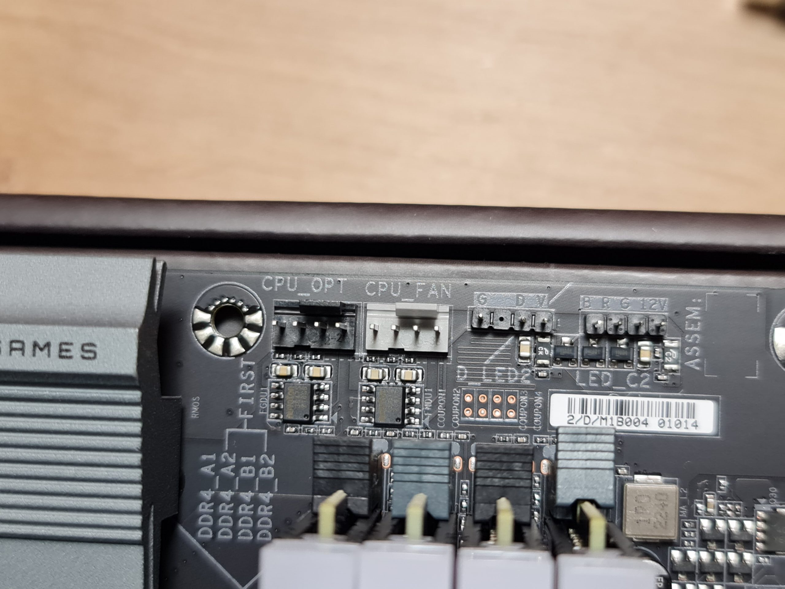
The final step is to plug in the power supply for the fan, and for this we again encourage you to take a peek at the motherboard manual to correctly locate the correct power connector for the CPU fan. The most common designation is “CPU FAN.” “CPU OPT”, on the other hand, refers to optional fans or the AiO pump in case there is no “CPU PUMP” connector.
Later in the material you will notice that the cooler of the AiO kit has been mounted unusually. If you are planning to install a similar CPU cooler, please note that the input/output connectors to the cooler should be slightly higher relative to the block-pump (the CPU-mounted component), so that the AiO cooler’s components do not seize up in the future.
This treatment was done intentionally to protect the cooler during transport, as the limited space on the top of the case does not allow the cooler to be fully stable, which could result in damage to the cooler or other components during transport. When the entire set is placed in its final location, the cooler will be lifted up to protect it from possible damage during operation.
Step 1.4 Mounting the optional M.2 drive
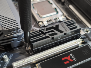
If you have an M.2 drive, it’s also a good idea to mount it at this point, so you don’t have to do it later with limited space through the case and graphics card. You’ll need to start by preparing a threaded stand for the M.2 drive at the end of it, then you just need to put the drive into the M.2 slot at an angle of about 45°, gently slide it in and press the back of the drive against the said stand. The next step will be to screw the drive on using the included screw.
- Initial assembly
- Tightening the mounting screw
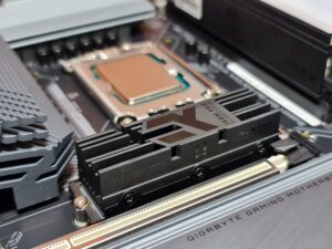
- Correctly installed IRDM PRO M.2 drive
For 2.5″ SATA SSD or 3.5″ SATA HDD, the opportunity to mount these types of drives will be a little later when preparing the case.
Step 2 Preparing the housing for installation
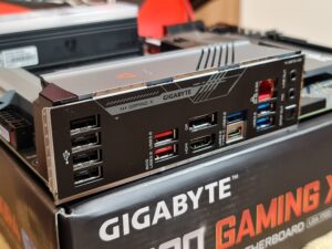
We encourage you to start preparing your case with the already legendary I/O cap for motherboard connectors, as this is the most often overlooked and forgotten item. The absence of this cap does not in any way hinder the computer and will not make our computer stop working, but the presence of this cap effectively reduces the amount of dust that gets into the case, so it is worth remembering it. You will find this cap in the box from the motherboard. All you need to do is unpack it and press it from the inside of the case with the appropriate side. In our case, the I/O port cap is permanently attached to the motherboard and is one with it.
- Installation location of the I/O cap in the case
- I/O cap on the motherboard
It may be useful to remove the connector caps for the graphics card. It is necessary to remove them at an appropriate height, so that you can later have the opportunity to connect the wiring to the graphics card, if you have a dedicated card.
Next, it is worth preparing the power supply in the case and most of the necessary wiring. At this stage, too, you need to think about the so-called cable management, in order to reign in the chaos of cables, because in the final form of the computer there will be some of them, and the order maintained positively affects the aesthetics of the whole kit and often also affects the airflow, that is, the correct air ventilation in the case, which can directly translate into temperatures and performance. All necessary cables should be routed through the back of the case if possible, and for this you can use the often present cable trays, adhesive tape or the popular “triptychs”, which are often included with the case. When dealing with a small case as in our case, it can be useful to prepare EPS cabling for the CPU power supply (“CPU” connector), GPU power supply (“PCIe” connector) and the always present ATX 24 PIN connector.
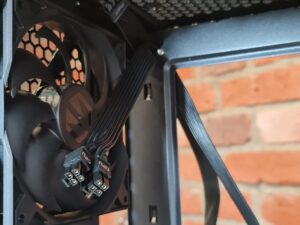
- CPU power cable
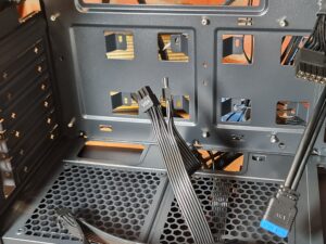
- GPU power cable
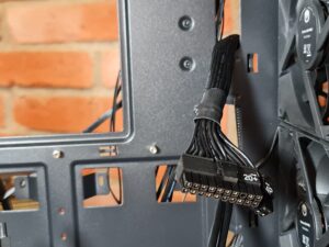
- Motherboard power cable
It is a good idea to pull the CPU power supply to the upper left corner of the case looking perpendicular to where the motherboard is mounted, the power supply to the card near the lower right corner, while the largest ATX connector to the right middle part of the motherboard.
- CPU cable in case
- MB cable in case
- GPU and USB cable in case
The power supply itself needs to be bolted to the case with dedicated mounting screws. Each case has only one designated place for this. Pay attention to the fan that is in the power supply, so that it has constant access to the air intakes after mounting. If the PSU is located at the bottom of the case and there are no filters from the bottom wall, mount the PSU with the fan facing the inside of the case, otherwise you can easily burn your PSU.
- PSU preparation
- Space for PSU
- Correct seating of PSU
- Screwing on PSU
- Correctly mounted PSU
After the mentioned steps, the power supply is ready to be connected to the motherboard.
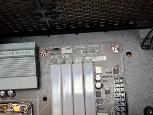
It is important to set the stands for later screwing the motherboard in the case. For this, it’s a good idea to bring yourself a previously prepared motherboard, so you can get to know the recesses where you need to prepare the threaded stands. So much for preparing the case, now it remains to put everything together.
Step 3 Mounting the motherboard inside the case
At this stage, something that already resembles a finished computer will slowly begin to emerge. The next step is to mount the previously prepared motherboard inside the case. All you need to do is lay the motherboard on the prepared stands and screw the whole board to the case with dedicated screws. Here a screwdriver with the ability to magnetically attract the screws will be very useful.
Pay attention to a good fit between the rear connectors on the motherboard and the I/O cap, so that no metal clip from the metal cap wraps around to the center of any of the ports, as you may later have problems connecting the desired devices to a particular port.
Step 3.1 Mount the drives
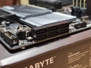
In the next step, after mounting the motherboard, there will be an opportunity to mount SATA drives (2.5″ or 3.5″), if you plan to have such in your computer. For this, you will need a SATA signal cable (most often found in red with black ends) and a SATA power cable, which I’m sure is already in your computer, as it is an integral part of any, even the most basic power supply.
- SATA power cable
- SATA signal connector
In our case, there were no SATA drives, so we will not present the exact connection process.
All you need to do is find a place to screw the drive if you want to mount it on the front of the case, that is, where the motherboard is already located (this option is only available for 2.5″ drives). Often, users who use mounting on this side of the case, i.e. “in plain sight”, are those who want to expose an interesting and nice SSD such as our IRDM PRO, for example! 😊
Almost every case has specially prepared drawers, which often come with quick-release fasteners specifically for 2.5″ and 3.5″ drives and do not require a single screw to keep the drive securely seated in one place.
Step 3.2 Installing the optional graphics card
If you are assembling a computer with gaming in mind, then most likely among all the components you are preparing there is also a graphics card. The card itself is theoretically optional, as we emphasize in the title of this assembly step, since most “blue” and “red” processors have an integrated graphics card (iGPU). Such a card will allow you to run the desktop without any problems, handle movies, the browser and that’s as much as it can afford. For gaming, dedicated graphics cards (GPU) are recommended, which allow you to achieve much better performance in games and demanding applications.
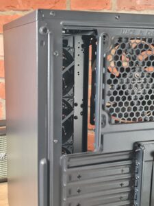
Before installing a graphics card, it is necessary to remove the “tracks”, or original caps, from the back of the case. If this was not done before mounting the motherboard to the case, it may be more difficult to do now.
What remains is the latch in the PCIe slot, where the graphics card will be seated. All you have to do is press it until it stays in the open position.
- PCIe connector
- PCIe latch pressure point
- Unlocked PCIe connector
At this point, all that’s left to do is to insert the graphics card into the PCIe slot, and the just-released latch will automatically snap into place. That’s not all, as an important step is to screw the GPU to the case in place of the previously removed “tracks”. For this, the identical screws used to screw the power supply to the case are most often used. With today’s cards, it is a good idea to use both (or three) places to tighten all the graphics, because modern graphics cards are very heavy, and their incorrect installation can result in imminent damage to the PCIe slot. In the future, consider adding a dedicated stand at the end of your card to prevent it from sagging.
In our case, we left the mere connection of the card to the PCIe slot to the very end, because we are dealing with a small case, and the presence of the GPU in a small case makes it even more difficult to connect all the necessary cables, which you will learn more about in the next step.
Step 4 – Connect all wires
Now it’s time for the final process of connecting all the signal and power cables. Most likely, you are dealing with new components, so pay attention to the fact that all the latches and other elements that secure the connectors in place are still unmachined, which will sometimes make it necessary to use a little more force to get each plug in place. Very often, a failure to fire up the computer for the first time is caused by an under-pressurized power cable for the board, CPU or incorrectly connected signal cables from the case, which we’ll get to in a moment.
Step 4.1 Powering up the motherboard
To fully power a motherboard you need the largest plug, which has 24 pins – it’s called an ATX connector.

All you need to do is to turn the previously prepared ATX cable the right way around, so that the latch on the connector coincides with the clip on the connector on the motherboard. Here it is impossible to insert the plug otherwise, because the square and round parts of specific pins are designed specifically for this. You may need to use a little more force to press it in correctly, so it would be a good idea to support the motherboard in place of the plug from the other side, so that there is no crack on the circuit board of the entire motherboard. When you hear the click of the latch, you can be sure that the plug has been pressed down correctly.
Step 4.2 Power the processor
The CPU power supply is most likely located in the upper left corner of the motherboard and you will need an EPS connector (signed as “CPU” on the power supply plug). The EPS connector consists of at least one 4-pin block. You may encounter connectors with more pins on motherboards that have a more powerful CPU power section. Such connectors can consist of plugs: 4 + 2 pins, 4 + 4 pins, or even 2 x (4 + 4 pins)!

When plugging in an EPS connector, the only and biggest problem may be the limited space around this connector. As with the ATX connector, it is important to reverse the connector with the latch towards the connector tab so that there is an opportunity for the latch to catch. Here, too, it is not possible to insert the connector the other way around, since the shape of the pins is specially designed so that such a problem does not arise. These shapes are universal for any motherboard and any power supply, so the situation will certainly not arise that any power supply will not fit any motherboard.
Step 4.3 Powering up the graphics card
A graphics card power cable, to the untrained eye, may deceptively resemble a CPU power cable, the previously mentioned EPS connector. The graphics card power supply you are most likely to encounter consists of two interconnecting 4 + 4 pin plugs. Some (weaker) cards will require only a single 4 pin cube, others (more powerful) 4 + 2 or 4 + 4 pin, while still other (most powerful) graphics cards may require two such 4 + 4 pin plugs.

Here there is nothing complicated, you just need to prepare the cables in advance, pulling them through the back of the case and plug them into the graphics card so that the snaps also coincide with each other, as in previous cases. Try not to strain or break the cables while plugging them in, especially if you are dealing with the latest cards from NV in the RTX 4000 series. When you hear the characteristic “click” just like in the previous situations, you can be sure that the power supply to the graphics card has been plugged in well.
Step 5 Connecting the chassis wiring
For those assembling a computer for the first time, this is usually one of the more intimidating stages. This involves hooking up the reset and power buttons and signal LEDs from the case. The problem is that most of the components (including the graphics card, which takes up a lot of space) are already installed in your computer, and the cables involved in this step are few and far between, but they are very small and single, and close together.
We are talking about cables such as:
POWER SWITCH – two, often separate cables that are designed to short two specific pins on the motherboard when you want to boot the computer;
RESET SWITCH – also two cables that are responsible for resetting the computer when you press the appropriate button on the case;
POWER LED – an LED that indicates a working computer;
HDD LED – a LED on the case that indicates the operation of the hard drive (increasingly rare).

Just glance at the manual or, for the more observant, at the motherboard itself and find a cluster of several pins having descriptions similar to the above (e.g. HDD L, RST SW, PWR SW, PW LED).

Just connect each wire according to the visible diagram to the motherboard. The only problem may be the small size of the wires and the fact that all the cables will be next to each other. Connecting them incorrectly will not threaten to damage the computer, but it may give the person assembling it at the finish a bit of fear, since the computer may not boot the first time from the button until the wires are just right.

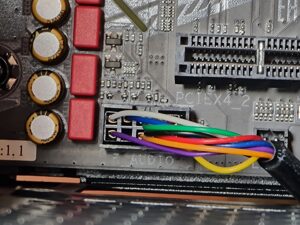
In addition to power and LEDs, there are also USB and female miniJack connectors on the cases, which also need to be connected to the motherboard somewhere. The connectors are called USB (wow!) and HD_AUDIO and are generally found on the lower left side of the motherboard.
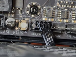
- Case fan connector
- AUDIO connector
- AUDIO cable
- USB 3.2 connector
- USB 3.2 cable
Jak zwykle zadbaj o porządek z przewodami podpinając je do złącza i tyle. Złącza te pasują tylko i wyłącznie jedną stroną, jak niemal wszystkie przewody, które dotychczas były przez Ciebie podłączane.
Summary
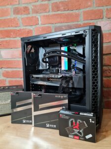
That’s it! You have successfully assembled your first computer. What’s left is to install the system, drivers and all the necessary programs. Below are some pictures of the finished unit:
However, if you’ve read this guide before ordering your hardware and are on the lookout for components for your first dream machine, take a look at our site, where you’ll find the most efficient SATA and M.2 SSDs, as well as fast and sensational-looking RAM modules! You can find this and much more HERE.
Remember also that after assembling your computer, it is necessary to install an operating system. To install such a system you may find it useful to use our USB, which you can also find HERE.
If there are any questions to any of the steps outlined or you would like to share an idea for another resource, you can find us at marketing@goodram.com or on our Facebook page – GOODRAM/IRDM.
